STM32 Logic Analyzer Day 1
2025-08-02
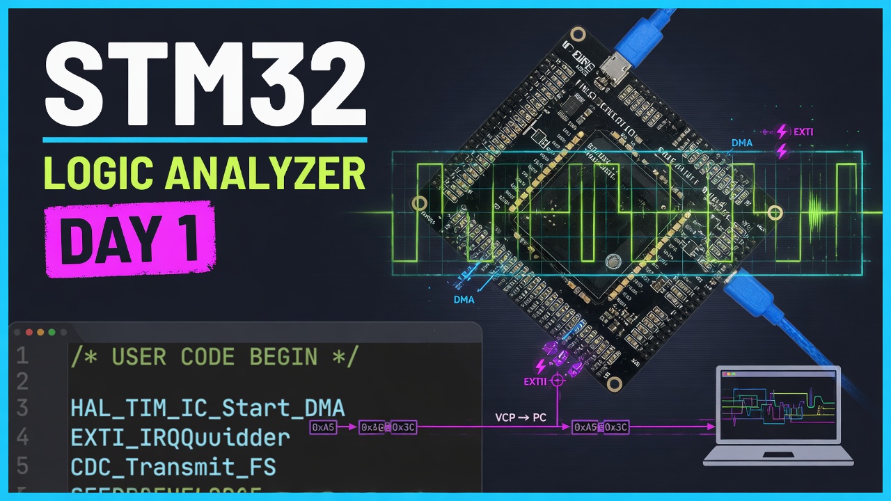
Trying to build a logic analyzer prototype, today i am using weact black pill board. I am using interrupt to fire the DMA and get the pins values, then use virtual com port to transfer it to PC, so far it works
/* USER CODE BEGIN Header */
/**
 ******************************************************************************
 * @file           : main.c
 * @brief          : Main program body
 ******************************************************************************
 * @attention
 *
 * Copyright (c) 2025 STMicroelectronics.
 * All rights reserved.
 *
 * This software is licensed under terms that can be found in the LICENSE file
 * in the root directory of this software component.
 * If no LICENSE file comes with this software, it is provided AS-IS.
 *
 ******************************************************************************
 */
/* USER CODE END Header */
/* Includes ------------------------------------------------------------------*/
#include "main.h"
#include "usb_device.h"

/* Private includes ----------------------------------------------------------*/
/* USER CODE BEGIN Includes */
#include <stdio.h>
#include <string.h>
/* USER CODE END Includes */

/* Private typedef -----------------------------------------------------------*/
/* USER CODE BEGIN PTD */

/* USER CODE END PTD */

/* Private define ------------------------------------------------------------*/
/* USER CODE BEGIN PD */

/* USER CODE END PD */

/* Private macro -------------------------------------------------------------*/
/* USER CODE BEGIN PM */

/* USER CODE END PM */

/* Private variables ---------------------------------------------------------*/
DMA_HandleTypeDef hdma_memtomem_dma2_stream0;
/* USER CODE BEGIN PV */

/* USER CODE END PV */

/* Private function prototypes -----------------------------------------------*/
void SystemClock_Config(void);
static void MX_DMA_Init(void);
static void MX_GPIO_Init(void);
/* USER CODE BEGIN PFP */

/* USER CODE END PFP */

/* Private user code ---------------------------------------------------------*/
/* USER CODE BEGIN 0 */
void XferCpltCallback(DMA_HandleTypeDef *hdma);
uint8_t Buffer_Src[] = { 0, 1, 2, 3, 4, 5, 6, 7, 8, 9 };
uint8_t Buffer_Dest[10];
volatile uint32_t gpio_value; // To store the 32-bit GPIO register value
volatile uint8_t transfer_complete = 0; // Flag to indicate transfer completion
/* USER CODE END 0 */

/**
 * @brief  The application entry point.
 * @retval int
 */
int main(void) {

	/* USER CODE BEGIN 1 */

	/* USER CODE END 1 */

	/* MCU Configuration--------------------------------------------------------*/

	/* Reset of all peripherals, Initializes the Flash interface and the Systick. */
	HAL_Init();

	/* USER CODE BEGIN Init */

	/* USER CODE END Init */

	/* Configure the system clock */
	SystemClock_Config();

	/* USER CODE BEGIN SysInit */

	/* USER CODE END SysInit */

	/* Initialize all configured peripherals */
	MX_DMA_Init();
	MX_GPIO_Init();
	MX_USB_DEVICE_Init();
	/* USER CODE BEGIN 2 */
	hdma_memtomem_dma2_stream0.XferCpltCallback = &XferCpltCallback;

	// Configure some GPIOA pins as inputs with pullup to see different values
	GPIO_InitTypeDef GPIO_InitStruct = { 0 };
	GPIO_InitStruct.Pin = GPIO_PIN_0 | GPIO_PIN_1 | GPIO_PIN_2 | GPIO_PIN_3 |
                          GPIO_PIN_4 | GPIO_PIN_5 | GPIO_PIN_6 | GPIO_PIN_7 |
                          GPIO_PIN_8 | GPIO_PIN_9 | GPIO_PIN_10 | GPIO_PIN_13 |
                          GPIO_PIN_14 | GPIO_PIN_15;  // All pins except PA11 and PA12
	GPIO_InitStruct.Mode = GPIO_MODE_INPUT;
	GPIO_InitStruct.Pull = GPIO_PULLDOWN;  // Pull up to see 1s in the register
	HAL_GPIO_Init(GPIOA, &GPIO_InitStruct);

	// Transfer 4 bytes (32-bit GPIO register) from GPIOA IDR to Buffer_Dest
	HAL_DMA_Start_IT(&hdma_memtomem_dma2_stream0, (uint32_t) &GPIOA->IDR,
			(uint32_t) Buffer_Dest, 4);
	/* USER CODE END 2 */

	/* Infinite loop */
	/* USER CODE BEGIN WHILE */
	while (1) {
		/* USER CODE END WHILE */

		/* USER CODE BEGIN 3 */

		// Check if DMA transfer completed
		if (transfer_complete) {
			// Format Buffer_Dest as human-readable hex string
    char hex_string[100];
//	memset(hex_string, 0, sizeof(hex_string));
//    CDC_Transmit_FS("Peter\r\n", 7);
//    CDC_Transmit_FS("HIH\r\n", 5);
    sprintf(hex_string, "0x%02X 0x%02X 0x%02X 0x%02X\r\n", Buffer_Dest[0], Buffer_Dest[1], Buffer_Dest[2], Buffer_Dest[3]);
//    sprintf(hex_string, "0x%02X\r\n", Buffer_Dest[0]);
    CDC_Transmit_FS(hex_string, strlen(hex_string));
//    CDC_Transmit_FS("END\r\n", 5);

			transfer_complete = 0; // Reset flag

			// At this point, you can examine:
			// - Buffer_Dest[0-3]: individual bytes from GPIOA->IDR
			// - gpio_value: reconstructed 32-bit value

			// Toggle LED2 to indicate transfer completed
//          HAL_GPIO_TogglePin(LD2_GPIO_Port, LD2_Pin);
//			HAL_GPIO_TogglePin(PB10_GPIO_Port, PB10_Pin);

			// Wait a bit before next transfer
//          HAL_Delay(1000);

			// Start another transfer
			HAL_DMA_Start_IT(&hdma_memtomem_dma2_stream0,
					(uint32_t) &GPIOA->IDR, (uint32_t) Buffer_Dest, 4);
		}
	}
	/* USER CODE END 3 */
}

/**
 * @brief System Clock Configuration
 * @retval None
 */
void SystemClock_Config(void) {
	RCC_OscInitTypeDef RCC_OscInitStruct = { 0 };
	RCC_ClkInitTypeDef RCC_ClkInitStruct = { 0 };

	/** Configure the main internal regulator output voltage
	 */
	__HAL_RCC_PWR_CLK_ENABLE();
	__HAL_PWR_VOLTAGESCALING_CONFIG(PWR_REGULATOR_VOLTAGE_SCALE1);

	/** Initializes the RCC Oscillators according to the specified parameters
	 * in the RCC_OscInitTypeDef structure.
	 */
	RCC_OscInitStruct.OscillatorType = RCC_OSCILLATORTYPE_HSE;
	RCC_OscInitStruct.HSEState = RCC_HSE_ON;
	RCC_OscInitStruct.PLL.PLLState = RCC_PLL_ON;
	RCC_OscInitStruct.PLL.PLLSource = RCC_PLLSOURCE_HSE;
	RCC_OscInitStruct.PLL.PLLM = 15;
	RCC_OscInitStruct.PLL.PLLN = 144;
	RCC_OscInitStruct.PLL.PLLP = RCC_PLLP_DIV4;
	RCC_OscInitStruct.PLL.PLLQ = 5;
	if (HAL_RCC_OscConfig(&RCC_OscInitStruct) != HAL_OK) {
		Error_Handler();
	}

	/** Initializes the CPU, AHB and APB buses clocks
	 */
	RCC_ClkInitStruct.ClockType = RCC_CLOCKTYPE_HCLK | RCC_CLOCKTYPE_SYSCLK
			| RCC_CLOCKTYPE_PCLK1 | RCC_CLOCKTYPE_PCLK2;
	RCC_ClkInitStruct.SYSCLKSource = RCC_SYSCLKSOURCE_PLLCLK;
	RCC_ClkInitStruct.AHBCLKDivider = RCC_SYSCLK_DIV1;
	RCC_ClkInitStruct.APB1CLKDivider = RCC_HCLK_DIV2;
	RCC_ClkInitStruct.APB2CLKDivider = RCC_HCLK_DIV1;

	if (HAL_RCC_ClockConfig(&RCC_ClkInitStruct, FLASH_LATENCY_1) != HAL_OK) {
		Error_Handler();
	}
}

/**
 * Enable DMA controller clock
 * Configure DMA for memory to memory transfers
 *   hdma_memtomem_dma2_stream0
 */
static void MX_DMA_Init(void) {

	/* DMA controller clock enable */
	__HAL_RCC_DMA2_CLK_ENABLE();

	/* Configure DMA request hdma_memtomem_dma2_stream0 on DMA2_Stream0 */
	hdma_memtomem_dma2_stream0.Instance = DMA2_Stream0;
	hdma_memtomem_dma2_stream0.Init.Channel = DMA_CHANNEL_0;
	hdma_memtomem_dma2_stream0.Init.Direction = DMA_MEMORY_TO_MEMORY;
	hdma_memtomem_dma2_stream0.Init.PeriphInc = DMA_PINC_ENABLE;
	hdma_memtomem_dma2_stream0.Init.MemInc = DMA_MINC_ENABLE;
	hdma_memtomem_dma2_stream0.Init.PeriphDataAlignment = DMA_PDATAALIGN_BYTE;
	hdma_memtomem_dma2_stream0.Init.MemDataAlignment = DMA_MDATAALIGN_BYTE;
	hdma_memtomem_dma2_stream0.Init.Mode = DMA_NORMAL;
	hdma_memtomem_dma2_stream0.Init.Priority = DMA_PRIORITY_VERY_HIGH;
	hdma_memtomem_dma2_stream0.Init.FIFOMode = DMA_FIFOMODE_ENABLE;
	hdma_memtomem_dma2_stream0.Init.FIFOThreshold = DMA_FIFO_THRESHOLD_FULL;
	hdma_memtomem_dma2_stream0.Init.MemBurst = DMA_MBURST_SINGLE;
	hdma_memtomem_dma2_stream0.Init.PeriphBurst = DMA_PBURST_SINGLE;
	if (HAL_DMA_Init(&hdma_memtomem_dma2_stream0) != HAL_OK) {
		Error_Handler();
	}

	/* DMA interrupt init */
	/* DMA2_Stream0_IRQn interrupt configuration */
	HAL_NVIC_SetPriority(DMA2_Stream0_IRQn, 0, 0);
	HAL_NVIC_EnableIRQ(DMA2_Stream0_IRQn);

}

/**
 * @brief GPIO Initialization Function
 * @param None
 * @retval None
 */
static void MX_GPIO_Init(void) {
	GPIO_InitTypeDef GPIO_InitStruct = { 0 };
	/* USER CODE BEGIN MX_GPIO_Init_1 */

	/* USER CODE END MX_GPIO_Init_1 */

	/* GPIO Ports Clock Enable */
	__HAL_RCC_GPIOH_CLK_ENABLE();
	__HAL_RCC_GPIOB_CLK_ENABLE();
	__HAL_RCC_GPIOA_CLK_ENABLE();

	/*Configure GPIO pin Output Level */
	HAL_GPIO_WritePin(PB10_GPIO_Port, PB10_Pin, GPIO_PIN_RESET);

	/*Configure GPIO pin : PB10_Pin */
	GPIO_InitStruct.Pin = PB10_Pin;
	GPIO_InitStruct.Mode = GPIO_MODE_OUTPUT_PP;
	GPIO_InitStruct.Pull = GPIO_NOPULL;
	GPIO_InitStruct.Speed = GPIO_SPEED_FREQ_LOW;
	HAL_GPIO_Init(PB10_GPIO_Port, &GPIO_InitStruct);

	/* USER CODE BEGIN MX_GPIO_Init_2 */
	// Configure GPIOA pins 0-7 as outputs driven low to ensure they read 0
//	GPIO_InitStruct.Pin = 0xFF;  // Pins 0-7
//	GPIO_InitStruct.Mode = GPIO_MODE_OUTPUT_PP;  // Output push-pull
//	GPIO_InitStruct.Pull = GPIO_NOPULL;
//	GPIO_InitStruct.Speed = GPIO_SPEED_FREQ_LOW;
//	HAL_GPIO_Init(GPIOA, &GPIO_InitStruct);
//
//	// Drive all pins low
//	HAL_GPIO_WritePin(GPIOA, 0xFF, GPIO_PIN_RESET);
	/* USER CODE END MX_GPIO_Init_2 */
}

/* USER CODE BEGIN 4 */
void XferCpltCallback(DMA_HandleTypeDef *hdma) {
	// Transfer completed - combine the 4 bytes to a 32-bit value for easier interpretation
	gpio_value = (Buffer_Dest[3] << 24) | (Buffer_Dest[2] << 16) | (Buffer_Dest[1] << 8) | Buffer_Dest[0];
	transfer_complete = 1;
	__NOP(); //Line reached only if transfer was successful. Toggle a breakpoint here
}
/* USER CODE END 4 */

/**
 * @brief  This function is executed in case of error occurrence.
 * @retval None
 */
void Error_Handler(void) {
	/* USER CODE BEGIN Error_Handler_Debug */
	/* User can add his own implementation to report the HAL error return state */
	__disable_irq();
	while (1) {
	}
	/* USER CODE END Error_Handler_Debug */
}
#ifdef USE_FULL_ASSERT
/**
  * @brief  Reports the name of the source file and the source line number
  *         where the assert_param error has occurred.
  * @param  file: pointer to the source file name
  * @param  line: assert_param error line source number
  * @retval None
  */
void assert_failed(uint8_t *file, uint32_t line)
{
  /* USER CODE BEGIN 6 */
  /* User can add his own implementation to report the file name and line number,
     ex: printf("Wrong parameters value: file %s on line %d\r\n", file, line) */
  /* USER CODE END 6 */
}
#endif /* USE_FULL_ASSERT */