Weact STM32H750 DMA Reg-To-Mem example
2025-07-23
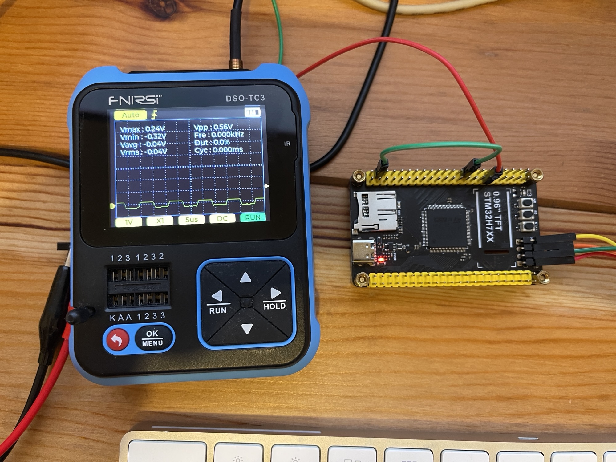
Few things need to be care and different then STM32F411CEU6
- You can use all 16 pins of GPIO-A but pins 15, 14, 13 are used already, see below image, they are always one
- Setting the max CPU freq 480 Mhz, if your program has bug, you can't burn the program again, follow this to solve https://peter.hkprog.org/2025/07/solved-weact-stm32h750vbt6-unable-to-find-target/
- What ever how high CPU freq, keep toggling the pin with DMA won't faster then 100KHz. Because DMA slow down the process. Even set the dma priority to "very high" won't help. Below code scale down toggling PC0 pin by 100x to provide this.
- Have to call __HAL_RCC_GPIOA_CLK_ENABLE(); before setup GPIO-A pins, STM32F411CEU6 no need
https://wiki.st.com/stm32mcu/wiki/Getting_started_with_DMA

/* USER CODE BEGIN Header */
/**
 ******************************************************************************
 * @file           : main.c
 * @brief          : Main program body
 ******************************************************************************
 * @attention
 *
 * Copyright (c) 2025 STMicroelectronics.
 * All rights reserved.
 *
 * This software is licensed under terms that can be found in the LICENSE file
 * in the root directory of this software component.
 * If no LICENSE file comes with this software, it is provided AS-IS.
 *
 ******************************************************************************
 */
/* USER CODE END Header */
/* Includes ------------------------------------------------------------------*/
#include "main.h"

/* Private includes ----------------------------------------------------------*/
/* USER CODE BEGIN Includes */

/* USER CODE END Includes */

/* Private typedef -----------------------------------------------------------*/
/* USER CODE BEGIN PTD */

/* USER CODE END PTD */

/* Private define ------------------------------------------------------------*/
/* USER CODE BEGIN PD */

/* USER CODE END PD */

/* Private macro -------------------------------------------------------------*/
/* USER CODE BEGIN PM */

/* USER CODE END PM */

/* Private variables ---------------------------------------------------------*/

DMA_HandleTypeDef hdma_memtomem_dma1_stream0;
/* USER CODE BEGIN PV */

/* USER CODE END PV */

/* Private function prototypes -----------------------------------------------*/
void SystemClock_Config(void);
static void MPU_Config(void);
static void MX_DMA_Init(void);
static void MX_GPIO_Init(void);
/* USER CODE BEGIN PFP */

/* USER CODE END PFP */

/* Private user code ---------------------------------------------------------*/
/* USER CODE BEGIN 0 */
void XferCpltCallback(DMA_HandleTypeDef *hdma);
uint8_t Buffer_Src[] = { 0, 1, 2, 3, 4, 5, 6, 7, 8, 9 };
uint8_t Buffer_Dest[10];
volatile uint32_t gpio_value; // To store the 32-bit GPIO register value
volatile uint8_t transfer_complete = 0; // Flag to indicate transfer completion
volatile uint32_t toggle_counter = 0; // Counter to slow down pin toggling
#define TOGGLE_DIVIDER 100 // Slow down by 100x
/* USER CODE END 0 */

/**
  * @brief  The application entry point.
  * @retval int
  */
int main(void)
{

  /* USER CODE BEGIN 1 */

  /* USER CODE END 1 */

  /* MPU Configuration--------------------------------------------------------*/
  MPU_Config();

  /* MCU Configuration--------------------------------------------------------*/

  /* Reset of all peripherals, Initializes the Flash interface and the Systick. */
  HAL_Init();

  /* USER CODE BEGIN Init */

  /* USER CODE END Init */

  /* Configure the system clock */
  SystemClock_Config();

  /* USER CODE BEGIN SysInit */

  /* USER CODE END SysInit */

  /* Initialize all configured peripherals */
  MX_DMA_Init();
  MX_GPIO_Init();
  /* USER CODE BEGIN 2 */
	hdma_memtomem_dma1_stream0.XferCpltCallback = &XferCpltCallback;

	// CRITICAL: Enable GPIOA clock first!
	__HAL_RCC_GPIOA_CLK_ENABLE();

	// Configure only a few safe GPIOA pins to test
	GPIO_InitTypeDef GPIO_InitStruct = { 0 };
	GPIO_InitStruct.Pin = GPIO_PIN_0 | GPIO_PIN_1 | GPIO_PIN_2 | GPIO_PIN_3 | GPIO_PIN_4 | GPIO_PIN_5;  // Just PA0 and PA1 for testing
	GPIO_InitStruct.Mode = GPIO_MODE_INPUT;
	GPIO_InitStruct.Pull = GPIO_PULLDOWN; // Pull down makes pins read as 0 when unconnected


	HAL_GPIO_Init(GPIOA, &GPIO_InitStruct);

	HAL_DMA_Start_IT(&hdma_memtomem_dma1_stream0, (uint32_t) &GPIOA->IDR,
			(uint32_t) Buffer_Dest, 4);
  /* USER CODE END 2 */

  /* Infinite loop */
  /* USER CODE BEGIN WHILE */
	while (1) {
    /* USER CODE END WHILE */

    /* USER CODE BEGIN 3 */
		// Check if DMA transfer completed
		if (transfer_complete) {
			transfer_complete = 0; // Reset flag

			// At this point, you can examine:
			// - Buffer_Dest[0-3]: individual bytes from GPIOA->IDR
			// - gpio_value: reconstructed 32-bit value

			// Increment counter and only toggle pin every TOGGLE_DIVIDER times
			toggle_counter++;
			if (toggle_counter >= TOGGLE_DIVIDER) {
				toggle_counter = 0; // Reset counter
				// Toggle LED to indicate transfer completed (slowed down 100x)
				HAL_GPIO_TogglePin(PC0_GPIO_Port, PC0_Pin);
			}

			// Wait a bit before next transfer
//			HAL_Delay(1000);

			// Start another transfer
			HAL_DMA_Start_IT(&hdma_memtomem_dma1_stream0,
					(uint32_t) &GPIOA->IDR, (uint32_t) Buffer_Dest, 4);
		}
	}
  /* USER CODE END 3 */
}

/**
  * @brief System Clock Configuration
  * @retval None
  */
void SystemClock_Config(void)
{
  RCC_OscInitTypeDef RCC_OscInitStruct = {0};
  RCC_ClkInitTypeDef RCC_ClkInitStruct = {0};

  /** Supply configuration update enable
  */
  HAL_PWREx_ConfigSupply(PWR_LDO_SUPPLY);

  /** Configure the main internal regulator output voltage
  */
  __HAL_PWR_VOLTAGESCALING_CONFIG(PWR_REGULATOR_VOLTAGE_SCALE0);

  while(!__HAL_PWR_GET_FLAG(PWR_FLAG_VOSRDY)) {}

  /** Initializes the RCC Oscillators according to the specified parameters
  * in the RCC_OscInitTypeDef structure.
  */
  RCC_OscInitStruct.OscillatorType = RCC_OSCILLATORTYPE_HSI;
  RCC_OscInitStruct.HSIState = RCC_HSI_DIV1;
  RCC_OscInitStruct.HSICalibrationValue = RCC_HSICALIBRATION_DEFAULT;
  RCC_OscInitStruct.PLL.PLLState = RCC_PLL_ON;
  RCC_OscInitStruct.PLL.PLLSource = RCC_PLLSOURCE_HSI;
  RCC_OscInitStruct.PLL.PLLM = 10;
  RCC_OscInitStruct.PLL.PLLN = 150;
  RCC_OscInitStruct.PLL.PLLP = 2;
  RCC_OscInitStruct.PLL.PLLQ = 2;
  RCC_OscInitStruct.PLL.PLLR = 2;
  RCC_OscInitStruct.PLL.PLLRGE = RCC_PLL1VCIRANGE_2;
  RCC_OscInitStruct.PLL.PLLVCOSEL = RCC_PLL1VCOWIDE;
  RCC_OscInitStruct.PLL.PLLFRACN = 0;
  if (HAL_RCC_OscConfig(&RCC_OscInitStruct) != HAL_OK)
  {
    Error_Handler();
  }

  /** Initializes the CPU, AHB and APB buses clocks
  */
  RCC_ClkInitStruct.ClockType = RCC_CLOCKTYPE_HCLK|RCC_CLOCKTYPE_SYSCLK
                              |RCC_CLOCKTYPE_PCLK1|RCC_CLOCKTYPE_PCLK2
                              |RCC_CLOCKTYPE_D3PCLK1|RCC_CLOCKTYPE_D1PCLK1;
  RCC_ClkInitStruct.SYSCLKSource = RCC_SYSCLKSOURCE_PLLCLK;
  RCC_ClkInitStruct.SYSCLKDivider = RCC_SYSCLK_DIV1;
  RCC_ClkInitStruct.AHBCLKDivider = RCC_HCLK_DIV2;
  RCC_ClkInitStruct.APB3CLKDivider = RCC_APB3_DIV2;
  RCC_ClkInitStruct.APB1CLKDivider = RCC_APB1_DIV2;
  RCC_ClkInitStruct.APB2CLKDivider = RCC_APB2_DIV2;
  RCC_ClkInitStruct.APB4CLKDivider = RCC_APB4_DIV2;

  if (HAL_RCC_ClockConfig(&RCC_ClkInitStruct, FLASH_LATENCY_4) != HAL_OK)
  {
    Error_Handler();
  }
}

/**
  * Enable DMA controller clock
  * Configure DMA for memory to memory transfers
  *   hdma_memtomem_dma1_stream0
  */
static void MX_DMA_Init(void)
{

  /* DMA controller clock enable */
  __HAL_RCC_DMA1_CLK_ENABLE();

  /* Configure DMA request hdma_memtomem_dma1_stream0 on DMA1_Stream0 */
  hdma_memtomem_dma1_stream0.Instance = DMA1_Stream0;
  hdma_memtomem_dma1_stream0.Init.Request = DMA_REQUEST_MEM2MEM;
  hdma_memtomem_dma1_stream0.Init.Direction = DMA_MEMORY_TO_MEMORY;
  hdma_memtomem_dma1_stream0.Init.PeriphInc = DMA_PINC_ENABLE;
  hdma_memtomem_dma1_stream0.Init.MemInc = DMA_MINC_ENABLE;
  hdma_memtomem_dma1_stream0.Init.PeriphDataAlignment = DMA_PDATAALIGN_BYTE;
  hdma_memtomem_dma1_stream0.Init.MemDataAlignment = DMA_MDATAALIGN_BYTE;
  hdma_memtomem_dma1_stream0.Init.Mode = DMA_NORMAL;
  hdma_memtomem_dma1_stream0.Init.Priority = DMA_PRIORITY_LOW;
  hdma_memtomem_dma1_stream0.Init.FIFOMode = DMA_FIFOMODE_ENABLE;
  hdma_memtomem_dma1_stream0.Init.FIFOThreshold = DMA_FIFO_THRESHOLD_FULL;
  hdma_memtomem_dma1_stream0.Init.MemBurst = DMA_MBURST_SINGLE;
  hdma_memtomem_dma1_stream0.Init.PeriphBurst = DMA_PBURST_SINGLE;
  if (HAL_DMA_Init(&hdma_memtomem_dma1_stream0) != HAL_OK)
  {
    Error_Handler( );
  }

  /* DMA interrupt init */
  /* DMA1_Stream0_IRQn interrupt configuration */
  HAL_NVIC_SetPriority(DMA1_Stream0_IRQn, 0, 0);
  HAL_NVIC_EnableIRQ(DMA1_Stream0_IRQn);

}

/**
  * @brief GPIO Initialization Function
  * @param None
  * @retval None
  */
static void MX_GPIO_Init(void)
{
  GPIO_InitTypeDef GPIO_InitStruct = {0};
  /* USER CODE BEGIN MX_GPIO_Init_1 */

  /* USER CODE END MX_GPIO_Init_1 */

  /* GPIO Ports Clock Enable */
  __HAL_RCC_GPIOC_CLK_ENABLE();

  /*Configure GPIO pin Output Level */
  HAL_GPIO_WritePin(PC0_GPIO_Port, PC0_Pin, GPIO_PIN_RESET);

  /*Configure GPIO pin : PC0_Pin */
  GPIO_InitStruct.Pin = PC0_Pin;
  GPIO_InitStruct.Mode = GPIO_MODE_OUTPUT_PP;
  GPIO_InitStruct.Pull = GPIO_NOPULL;
  GPIO_InitStruct.Speed = GPIO_SPEED_FREQ_LOW;
  HAL_GPIO_Init(PC0_GPIO_Port, &GPIO_InitStruct);

  /* USER CODE BEGIN MX_GPIO_Init_2 */

  /* USER CODE END MX_GPIO_Init_2 */
}

/* USER CODE BEGIN 4 */
void XferCpltCallback(DMA_HandleTypeDef *hdma) {
	// Transfer completed - combine the 4 bytes to a 32-bit value for easier interpretation
	gpio_value = (Buffer_Dest[3] << 24) | (Buffer_Dest[2] << 16)
			| (Buffer_Dest[1] << 8) | Buffer_Dest[0];

	// For debugging: you can examine individual bytes here
	// Buffer_Dest[0] = LSB of GPIOA->IDR (pins PA0-PA7)
	// Buffer_Dest[1] = pins PA8-PA15
	// Buffer_Dest[2] = pins PA16-PA23 (if available)
	// Buffer_Dest[3] = MSB of GPIOA->IDR (pins PA24-PA31, if available)

	transfer_complete = 1;
	__NOP(); //Line reached only if transfer was successful. Toggle a breakpoint here
}
/* USER CODE END 4 */

 /* MPU Configuration */

void MPU_Config(void)
{
  MPU_Region_InitTypeDef MPU_InitStruct = {0};

  /* Disables the MPU */
  HAL_MPU_Disable();

  /** Initializes and configures the Region and the memory to be protected
  */
  MPU_InitStruct.Enable = MPU_REGION_ENABLE;
  MPU_InitStruct.Number = MPU_REGION_NUMBER0;
  MPU_InitStruct.BaseAddress = 0x0;
  MPU_InitStruct.Size = MPU_REGION_SIZE_4GB;
  MPU_InitStruct.SubRegionDisable = 0x87;
  MPU_InitStruct.TypeExtField = MPU_TEX_LEVEL0;
  MPU_InitStruct.AccessPermission = MPU_REGION_NO_ACCESS;
  MPU_InitStruct.DisableExec = MPU_INSTRUCTION_ACCESS_DISABLE;
  MPU_InitStruct.IsShareable = MPU_ACCESS_SHAREABLE;
  MPU_InitStruct.IsCacheable = MPU_ACCESS_NOT_CACHEABLE;
  MPU_InitStruct.IsBufferable = MPU_ACCESS_NOT_BUFFERABLE;

  HAL_MPU_ConfigRegion(&MPU_InitStruct);
  /* Enables the MPU */
  HAL_MPU_Enable(MPU_PRIVILEGED_DEFAULT);

}

/**
  * @brief  This function is executed in case of error occurrence.
  * @retval None
  */
void Error_Handler(void)
{
  /* USER CODE BEGIN Error_Handler_Debug */
	/* User can add his own implementation to report the HAL error return state */
	__disable_irq();
	while (1) {
	}
  /* USER CODE END Error_Handler_Debug */
}
#ifdef USE_FULL_ASSERT
/**
  * @brief  Reports the name of the source file and the source line number
  *         where the assert_param error has occurred.
  * @param  file: pointer to the source file name
  * @param  line: assert_param error line source number
  * @retval None
  */
void assert_failed(uint8_t *file, uint32_t line)
{
  /* USER CODE BEGIN 6 */
  /* User can add his own implementation to report the file name and line number,
     ex: printf("Wrong parameters value: file %s on line %d\r\n", file, line) */
  /* USER CODE END 6 */
}
#endif /* USE_FULL_ASSERT */